Contents
- What Does a Rectifier Do in a Substation?
- What Is the Difference Between 110V DC and 220V DC Rectifiers?
- 7 Key Criteria When Choosing a Substation Rectifier
- How Do the Rectifier, Battery Bank and DC Distribution Work Together?
- Fault Warning Signs: When to Act
- Which Standards Apply to Substation Rectifiers?
- What Information Is Needed Before Buying?
- Frequently Asked Questions About Substation Rectifiers
In substations, power plants and electricity distribution facilities, a reliable energy infrastructure is more than the main grid supply. During a fault, the protection relay must detect the fault and trip the circuit breaker within milliseconds. But if the fault is on the grid itself and the AC supply has been lost, what energy does this rely on? The answer: a DC auxiliary power system made up of a rectifier and a battery bank.
110V DC and 220V DC rectifiers in particular are used in energy facilities to supply DC auxiliary loads and keep battery banks charged. However, choosing a rectifier for a substation takes more than determining the nominal voltage; load current, battery capacity, backup time, protection features and operating conditions must be assessed together. In this guide we go through these criteria step by step.
What Does a Rectifier Do in a Substation?
Many critical items of equipment in substations run on DC auxiliary power:
- Protection relays
- Circuit breaker trip and close coils, disconnector motors
- Control, command and signalling circuits
- SCADA, RTU, remote control and communication equipment
- Alarm systems and emergency lighting
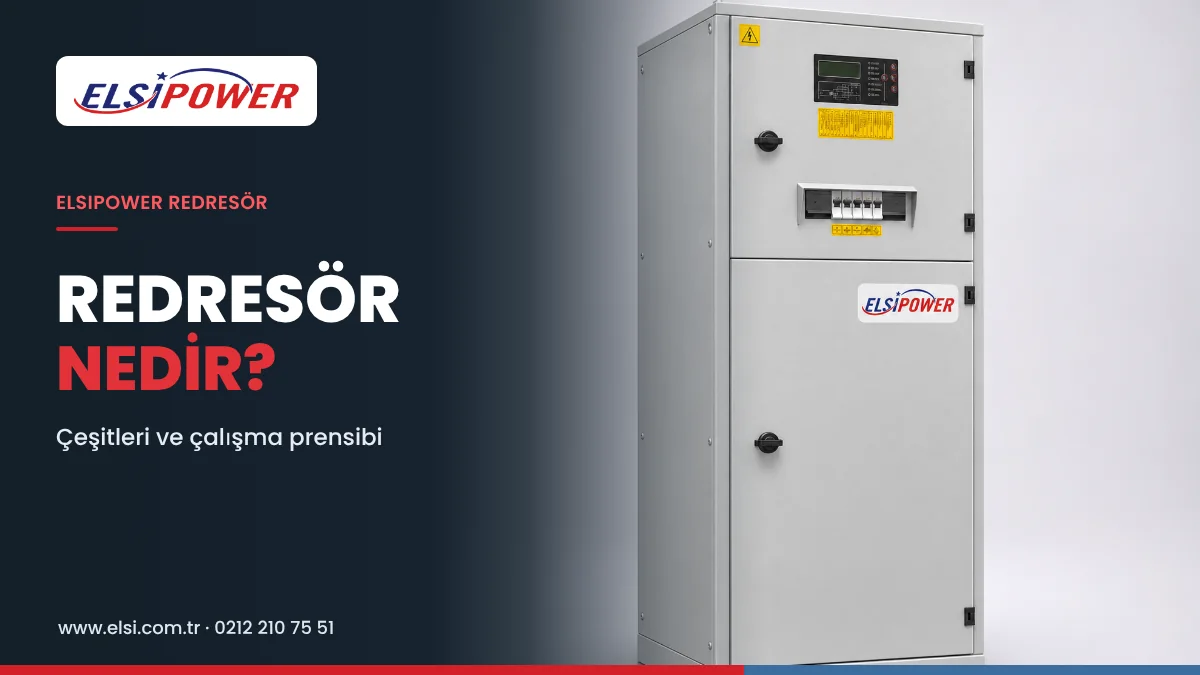
The rectifier’s main task is to convert AC mains energy into suitable DC energy to supply these loads and keep the connected battery bank charged. When the mains is lost, the battery bank takes over with no transfer time and keeps the loads running for the specified period. We explain the general operating principle of a rectifier in What Is a Rectifier?
What Is the Difference Between 110V DC and 220V DC Rectifiers?
DC auxiliary power systems in energy facilities are designed at different nominal voltages; 110V DC and 220V DC are the most common.
| Feature | 110V DC system | 220V DC system |
|---|---|---|
| Typical application | Substations, protection and control circuits | Power plants, switchyards, auxiliary DC systems |
| Battery bank | Designed for the 110V system | Designed for the 220V system |
| Output current | Determined by the project | Determined by the project |
| Charge control | Suited to the battery type | Suited to the battery type |
Which voltage is used depends on the facility’s electrical design and equipment. A control circuit designed for 110V DC cannot be supplied from 220V DC without suitable conversion and protection, so the nominal DC system voltage must be fixed in the first step. Also, the nominal voltage and the actual operating voltage are not always the same: the DC bus voltage varies within certain limits depending on the battery’s charge and discharge state. Some facilities have a separate 48V DC system for communications alongside 110V DC for protection and control.
7 Key Criteria When Choosing a Substation Rectifier
1. Calculating the DC load current
First, the total current of protection relays, control equipment, communication systems and other continuous loads is calculated. Short, high-current loads such as breaker trip and close coils are examined separately; these surge currents are mostly supplied by the battery bank, but the battery capacity and DC distribution must be sized for them.
2. Battery charging capacity
In normal operation the rectifier charges the battery bank while supplying the DC loads, so the charging requirement must be included when determining the total output current:
- Required rectifier current = DC load current + planned battery charging current
- For example, a system with a 25A continuous load and a 15A charging requirement needs at least 40A of output current to meet both at the same time.
This value is a first assessment. Transient loads, voltage limits, ambient conditions, design margin and redundancy are calculated separately for the final selection. You can find the general calculation method with examples in Rectifier Prices 2026 and Selection Guide.
3. Battery type and backup time
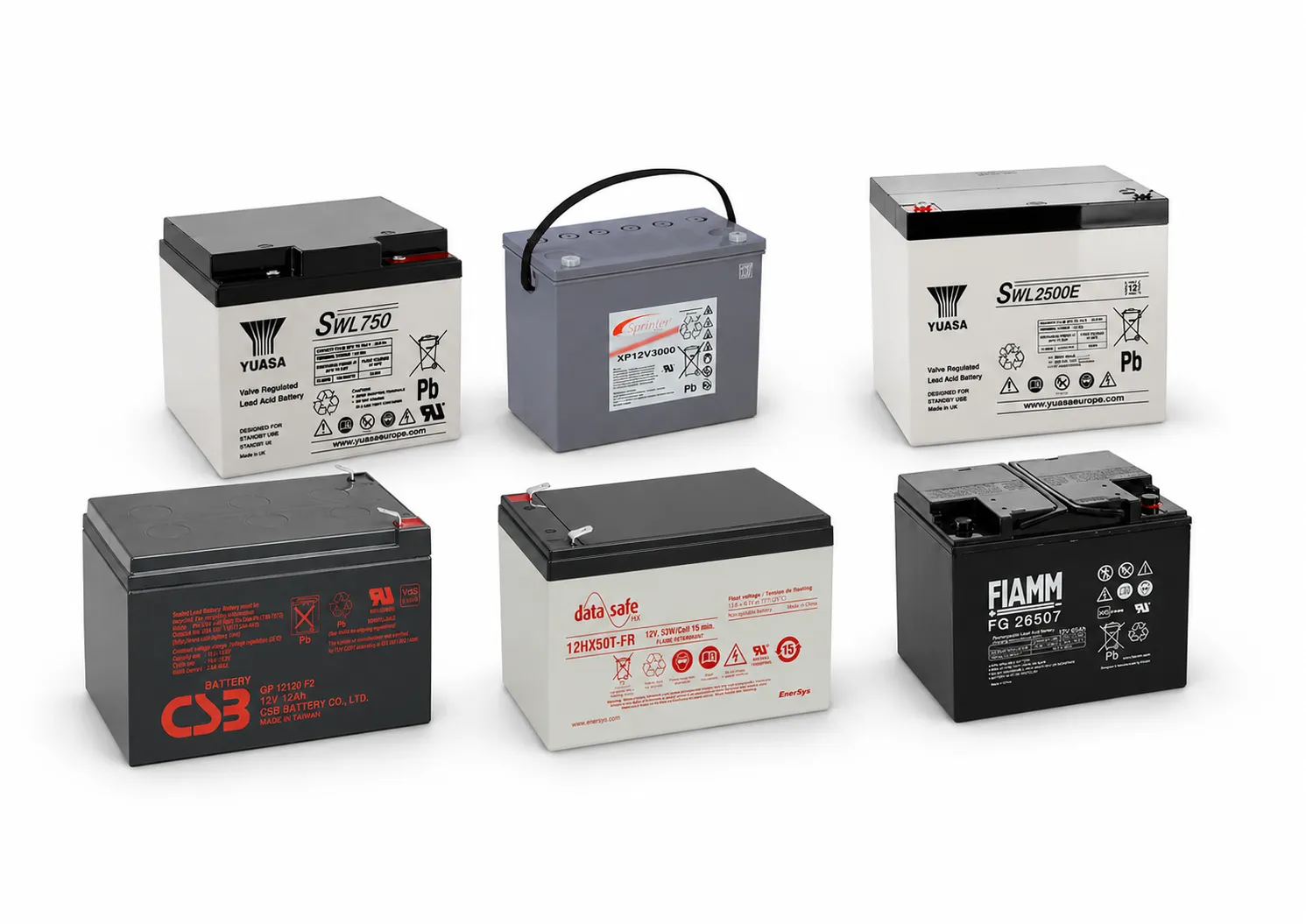
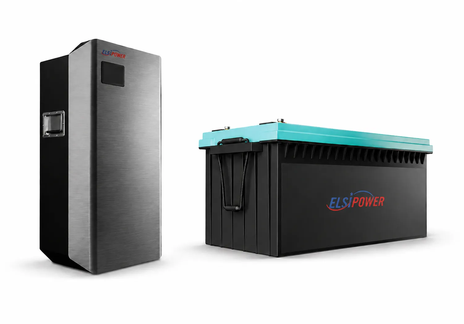
Lead-acid (maintenance-free VRLA/AGM or vented) and nickel-cadmium batteries are common choices in substations. When determining battery capacity, consider:
- The run time required during a power outage
- Continuous and short-duration DC loads
- The discharge characteristics of the batteries
- Ambient temperature
- Battery ageing and capacity loss
- The minimum DC voltage allowed for the system
For example, a 1-hour and a 4-hour backup requirement do not need the same battery capacity. The actual capacity is calculated from the load profile and the battery manufacturer’s discharge tables. See our battery solutions for battery options.
4. Redundant rectifier system
In substations where power continuity is critical, a single rectifier is an operating risk if it fails. Redundant arrangements are therefore preferred depending on the project:
- N+1 redundancy: The system is designed so that the remaining modules can carry the defined load if one rectifier module is out of service.
- Two rectifiers and two battery banks: One side can be taken out of service during maintenance or a fault.
When choosing a redundant arrangement, module capacity, current sharing, maintenance options and failure scenarios are assessed.
5. Protection and alarm features
Detecting faults quickly is at least as important as conversion performance. For an industrial rectifier suited to the project, the following functions are considered:
- Overcurrent and short circuit protection
- Output over/under voltage alarm
- Rectifier fault indication and dry contact alarm outputs
- Battery charge monitoring
- Overtemperature protection
- Transfer to SCADA and remote monitoring options
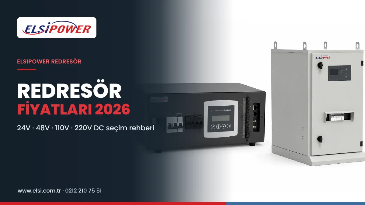
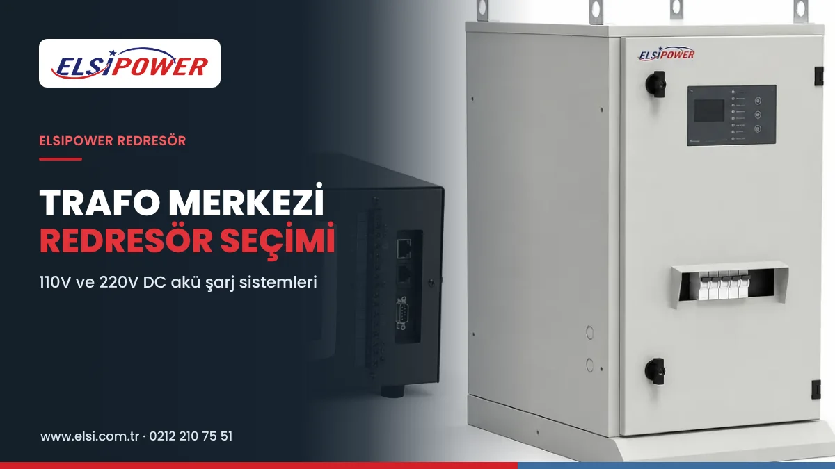
ELSIPOWER rectifiers feature constant voltage output, current limiting, short circuit, overload, overtemperature and reverse polarity protection, a rectifier fault signal output, a boost charge input and LED status indicators.
6. Cabinet design and operating environment
Ambient temperature, dust, humidity and ventilation directly affect the life of the rectifier and the batteries. The ingress protection (IP) rating, cable entries, maintenance access and cooling design are set according to project requirements. Electrical safety and ventilation needs must be considered when positioning battery banks.
7. Technical service and periodic maintenance
Most problems in a DC system develop silently: a battery gradually loses capacity, a connection oxidises or a fan clogs with dust. The problem only shows up when the mains fails. Periodic maintenance checks:
| Check | Why it matters |
|---|---|
| Output voltage and current settings | Wrong settings undercharge or overcharge the battery |
| Float and boost charge values | They must match the battery manufacturer’s recommendations |
| Alarm and fault signal test | Ensures that alarms reach the control room during a fault |
| Fan, cooling and dust cleaning | Overheating shortens rectifier and battery life |
| Connection and terminal checks | Loose or oxidised connections cause heating and voltage drop |
| Battery voltages and temperature | Weakening batteries are detected early |
| Battery capacity (discharge) test | Shows whether the battery bank lasts the required time |
Recording measurement results makes it possible to plan battery replacement in advance. At ELSIPOWER we provide site surveys, installation and periodic maintenance for rectifier and battery bank projects; see our technical service page for details.
How Do the Rectifier, Battery Bank and DC Distribution Work Together?
| Component | Role |
|---|---|
| Rectifier | Converts the AC mains into stable DC, supplies the loads and manages battery charging |
| Battery bank | Supplies the DC bus when the mains fails and meets the momentary high current of breaker coils |
| DC distribution board | Distributes power to the loads through fused/protected outgoing circuits |
| Monitoring and alarms | Reports conditions such as rectifier failure or low voltage to the control room and SCADA |
That is why the health of the battery bank and the reliability of DC distribution matter as much as the rectifier’s capacity. Batteries that have lost capacity, connection problems or faulty protection equipment reduce backup performance even when the rectifier is working.
Fault Warning Signs: When to Act
- The rectifier fault LED is lit or an alarm reaches SCADA
- The DC bus voltage is below or above its normal value
- The battery bank is constantly charging at high current
- Battery swelling, heating, leakage or odour
- Unusual noise from the rectifier fan or overheating
- Battery voltage dropping quickly even during a short outage
Checking the system without delay when any of these signs appears prevents the protection system from being out of service during a possible grid fault.
Which Standards Apply to Substation Rectifiers?
Relevant technical standards and facility specifications must be considered when designing industrial DC power systems. For example, IEC 62485-2 covers safety aspects of stationary battery installations such as electrical hazards, gas emission, electrolyte and ventilation. Depending on the battery type and project, relevant battery standards, protection equipment requirements and the facility’s electrical specification are also assessed. The rectifier, battery bank and DC distribution system should be treated as a whole.
What Information Is Needed Before Buying?
| Required information | Description |
|---|---|
| DC system voltage | 110V, 220V or another project value |
| Input supply | Single-phase or three-phase AC |
| Continuous DC load current | Normal operating current |
| Transient loads | Breaker coils and other short-duration loads |
| Battery bank | Battery type, number of cells and Ah rating |
| Backup time | Target run time during a power outage |
| Redundancy | Single or redundant system |
| Monitoring and alarms | SCADA, dry contact and communication requirements |
If an existing unit is being replaced, the rectifier’s rating plate, battery bank details and electrical drawings are particularly useful.
Frequently Asked Questions About Substation Rectifiers
Why are DC systems used in substations?
A DC auxiliary power system allows protection and control circuits to be backed up by batteries, so critical equipment keeps working even when the AC supply is lost.
Can a 220V DC rectifier be used instead of 110V DC?
Not directly. The voltage compatibility of protection relays, breaker coils and other DC equipment must be checked; changing the voltage requires a thorough engineering assessment.
How many amps should a substation rectifier be?
The output current is determined by the continuous DC loads, the battery charging requirement and operating conditions. There is no single amp rating that suits every substation.
What happens if the rectifier fails?
In single-rectifier systems, the battery bank supplies the loads for a while depending on its capacity. In redundant systems the other rectifier continues the supply. If the fault is not cleared, the batteries discharge and the system can lose power, which is why passing the rectifier fault signal to the control room is important.
How often should the battery bank be checked?
The frequency is set in the maintenance plan according to the criticality of the facility, the battery type and ambient conditions. In critical facilities, regular measurements and planned repetition of capacity tests are recommended.
Can the existing batteries be used when the rectifier is replaced?
Yes, if the type, age and test results of the batteries are suitable. We recommend measuring the batteries’ capacity condition before the changeover.
DC system support for your substation
As ELSİ Güç Sistemleri, under our ELSIPOWER brand we provide rectifier and battery bank solutions for substations, energy facilities and switchgear systems. Share your technical requirements with us for a new 110V or 220V DC system, renewal of an existing rectifier or periodic maintenance. 0212 210 75 51 · elsi@elsi.com.tr